
Why AV racks overheat even when the room feels cool
An AV rack concentrates heat from processors, amplifiers, network switches, encoders, decoders, control hardware and power equipment into a small enclosure. The room thermostat may report an acceptable average while the top of a closed rack, a blocked device intake or a side-breathing switch operates much hotter.
Common causes are practical: the installed load differs from the design, HVAC stops after hours, exhaust returns to an intake, cables obstruct ventilation, rack spaces remain open, or added fans oppose equipment airflow. An AV integrator in China should coordinate the rack, room and operating model as one thermal system.
Calculate heat from the real electrical load
Start with an equipment schedule recording manufacturer power data, expected operating state and where each watt is dissipated. Nameplate maximums define an upper boundary, but measured input power under a representative busy condition gives a better operating baseline.
For a practical conversion, multiply watts by about 3.42 to estimate BTU per hour. A measured 1,000 W rack load therefore represents roughly 3,420 BTU/h of heat. Add losses from UPS equipment or other power devices located in the same room using their manufacturer data. Do not automatically count the full downstream load twice.
The calculation is an input to an HVAC engineer, not a complete cooling design. Allow for simultaneous operation, future capacity, room heat sources and fault conditions. Sinoway's UPS design guide for AV racks in China explains why power, runtime and thermal planning need the same load record.

Define the room conditions and HVAC operating schedule
A rack cannot reject heat into a room that has nowhere to send it. Confirm the supply-air location, return path, room volume, door and grille conditions, adjacent heat sources and whether the HVAC runs whenever the AV equipment remains energised. Office comfort cooling that shuts down at night or during public holidays can leave an always-on rack without a viable heat path.
Write the required operating hours and facilities owner into the design. If continuous room cooling is not justified, define which devices may shut down, how they restart and how the remaining load is monitored. Dust, humidity, noise and access also influence the cooling method.
Map every device's airflow direction before adding fans
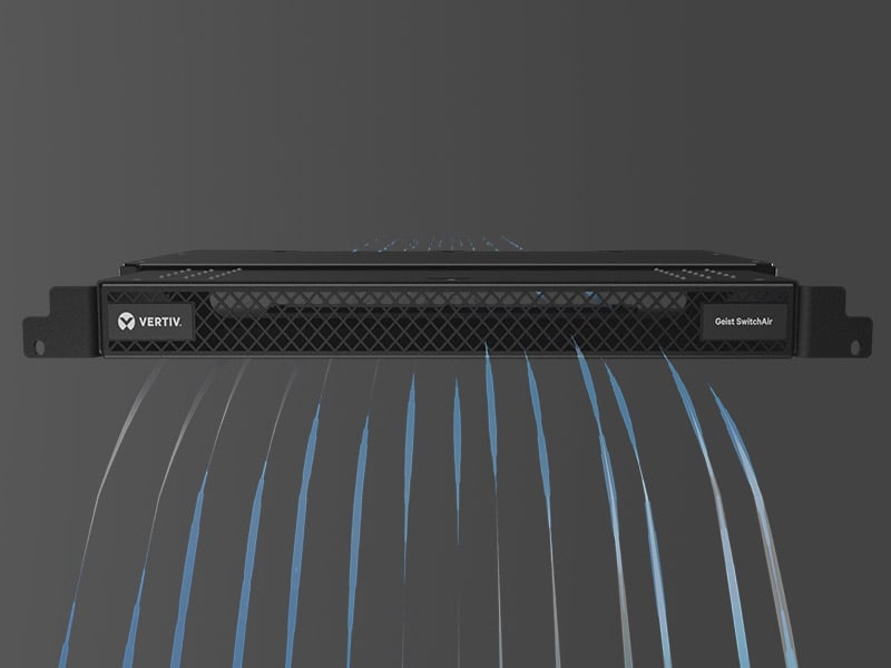
Most rack equipment moves air front-to-rear, but some switches breathe side-to-side, amplifiers may exhaust vertically, and compact devices may rely on convection. Record every intake and exhaust on the rack elevation. A fan tray helps only when it reinforces a complete path to the room return.
Do not place an exhaust against a solid panel or another device's intake. Maintain manufacturer clearances. For side-breathing equipment, use a layout or air channel that prevents hot rear air returning to the intake. Establish the intended heat path before changing fan direction.

Control recirculation, blank spaces and cable obstructions
Open rack units and unsealed cable passages allow hot exhaust to return toward equipment intakes. Fit blanking panels where the airflow strategy requires separation, close unnecessary openings, and keep rear cable bundles away from fan outlets. Fully perforated doors are useful only when the room supplies and removes enough air through them.
Cable management is thermal management. Preserve bend radius, service loops and connector access without forming a wall behind equipment. Keep power supplies and dense cable looms away from exhausts. After every move, add or change, recheck blanking panels, penetrations and airflow direction.
Place temperature sensors where equipment receives air
A single wall thermostat cannot describe conditions inside a rack. Measure at the equipment intake and check the front and rear at the top, middle and bottom of the enclosure. Compare those readings with device telemetry where available. The top-front intake often reveals recirculation, while a high rear reading may simply confirm that heat is being removed as intended.
Set warning and critical thresholds from project requirements and device limits, not one universal target. Trend occupied hours, overnight operation and HVAC schedule changes. Record sensor positions so future readings remain comparable.
Commission the rack under representative operating conditions
Thermal acceptance should be a measured test, not a visual inspection. Close the rack doors and panels, run the expected combination of equipment, confirm the room HVAC state, and allow temperatures to stabilise. Exercise high-load modes such as amplifiers driving programme audio, codecs in active calls and network devices carrying normal traffic.
Record power, room supply and return conditions, and the six rack measurement points. Check fan operation, thermostatic controls, filters, blocked-fan alarms and temperature alerts. Test the agreed response to an HVAC interruption or fan failure only within a controlled plan that protects the equipment. A 24-hour logger is valuable where building cooling changes after working hours.
Record the installed configuration, test load, instruments, sensor locations, readings and criteria. If the system fails, correct the airflow or room cooling and repeat the test rather than masking a hot spot by lowering the whole building setpoint.
- Reconcile installed devices and power readings with the final rack elevation.
- Verify every intake and exhaust has the required clearance.
- Confirm doors, blanking panels, cable entries and fan directions match the design.
- Test temperature alarms and document who receives them.
- Repeat the readings after corrective work and retain both results.
Make thermal performance maintainable after handover
The handover should include the heat-load worksheet, rack elevation, airflow map, HVAC dependency, schedule, temperature limits, sensor map, alarm destinations and test results. Add cleaning intervals, filter and fan part numbers, access instructions and the change-approval process.
Update the AV rack labelling and documentation guide whenever devices move or power and airflow assumptions change. Facilities, IT and AV support should each know their boundary: who maintains room cooling, who responds to alerts, who can change the rack, and who signs off a new thermal baseline. That ownership is what keeps a compliant rack dependable after the project team leaves.