
Define the LED acceptance plan before final calibration
Start with the approved design, product data, shop drawings and method statement. List the finished image dimensions, native pixel canvas, cabinet and module quantities, controller topology, input formats, viewing positions, ambient-light conditions, operating modes and content types. State which party owns structural, electrical, network, processor, content and display tests. An AV integrator in China should coordinate those boundaries before commissioning so a fault cannot disappear between trades.
Write measurable pass criteria into the schedule. These may include allowable pixel defects, cabinet alignment, brightness, colour temperature, uniformity, refresh rate, latency, acoustic noise, temperature, power draw and recovery behaviour. Use the contracted manufacturer specification and project requirements. Absen’s current quality framework, for example, publishes its own brightness, chromaticity, colour and alignment values; those are useful evidence for that product family, not automatic limits for every LED wall. Record the instrument, test pattern, measurement position and warm-up condition for each quantitative test.
Inspect structure, cabinet alignment and the visible image plane
Inspect the supporting structure before judging picture quality. Confirm fixing locations, load paths, levelling, cabinet locks, safety restraints, earthing, cable strain relief, ventilation clearances and the finished relationship to surrounding walls and joinery. Check that service panels can open and that a module, power supply or receiving card can be removed without damaging adjacent finishes. Photograph concealed work and record any structural sign-off required by the project.
View the unlit surface and full-screen black, white, red, green, blue and mid-grey patterns from the agreed audience positions. Look for stepped cabinets, uneven gaps, bowed planes, bright or dark lines, colour blocks and reflected light that changes across the wall. Then display a fine grid and circles at the native canvas. AVIXA’s verification guidance recommends geometry patterns, operation at native and intended resolutions, representative source material and checks from multiple viewing locations. The evidence should show the whole wall and close details, not only a flattering wide photograph.

Test the complete signal path at every intended format
Send patterns and real content through the production path: source, switcher, scaler, wall processor, controller, receiving cards and modules. Confirm input detection, scaling, aspect ratio, frame-rate handling, colour range, bit depth, HDR or SDR mode where specified, and the final pixel mapping. Test all contracted resolutions and frame rates rather than only the installer’s laptop. Cropped edges, duplicated rows, soft text or incorrect colour may originate upstream even when the cabinets themselves are healthy.
Use content that exposes different weaknesses: small text and one-pixel lines for mapping and focus, slow gradients for banding, dark scenes for low-grey consistency, bright scenes for clipping and thermal behaviour, and motion for processing artefacts. If several windows or sources are part of the design, load the maximum planned layout and recall every operational preset. Save photographs of patterns and screenshots of controller mapping so the result can be reproduced after handover.

Check pixels, seams, uniformity and calibration separately
Count and map dead, stuck, dim or unstable pixels using the agreed solid-colour sequence and observation distance. Do not hide a defect by changing content or brightness. Compare the result with the contract and manufacturer policy, then record repaired modules and retest them. Inspect seams independently: a smooth white field may reveal brightness lines, while black and low-grey fields show surface, coating and module-to-module differences that bright content can conceal.
Measure brightness, colour temperature and chromaticity at the specified points after the display has stabilised. Review uniformity both numerically and visually, including corners and replaced modules. Calibration is not a one-time cosmetic adjustment: it creates coefficients tied to cabinets, modules or pixels. NovaStar documentation distinguishes screen, cabinet, module and pixel coefficient management and advises backing up calibration data. Retain the baseline before changes, the accepted database afterwards and a clear method for applying the correct data to a replacement part.
Verify refresh, cameras, latency and continuous operation
Where the wall will appear on camera, test it with the actual camera chain or representative equipment. Record the intended frame rate, shutter angle or speed, scan mode and processor settings. Look for rolling bands, flicker, scan lines, moiré and colour shifts at typical shot sizes. A refresh-rate figure on a data sheet does not guarantee an acceptable photographed result because camera timing, brightness, driver behaviour and processing interact.
Run the display with demanding content long enough to reach a stable operating condition. Watch controller alarms, receiving-card communication, module temperature, fan behaviour and visible changes as the wall warms. Exercise scheduled on/off control and confirm the approved start-up and shutdown sequence. If the project specifies latency, power, temperature or acoustic limits, measure them with suitable instruments and save the readings. NovaStar’s published QA examples include brightness, refresh rate, maximum frame rate, camera tests, stability, thermal compensation and calibration-coefficient management, illustrating why acceptance needs more than a short visual check.
Prove maintenance access, spares and fault recovery
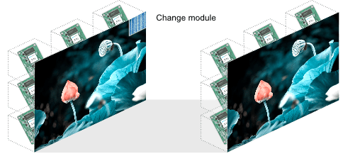
Perform a witnessed module replacement using the intended access method. Confirm that the correct spare fits, tools can reach the part safely, connectors are keyed and labelled, and the replacement returns to the accepted brightness and colour without disturbing neighbouring modules. Repeat the logic for power supplies, receiving cards, data links and controller outputs where the design requires field replacement. Spares should be identified by exact part number, batch or calibration relationship and storage condition.
Test resilience deliberately. Disconnect the approved redundant signal or control path, interrupt a defined component and confirm the display responds as designed. Verify alarms, failover, restoration and the operator procedure. Do not create an unsafe electrical test or remove protection simply to demonstrate recovery. Record which failures are transparent, which reduce performance and which require a controlled shutdown. The acceptance report should show both the successful recovery and any limitation users must understand.
Deliver evidence that supports the LED wall after handover
The handover pack should include approved drawings, cabinet and module maps, serial and asset records, controller and receiving-card topology, power distribution, network addresses, firmware and software versions, licence information, calibration databases, configuration files, processor presets, test results, defect history, photographs, spares schedule, warranty documents and safe maintenance procedures. Store editable native files as well as readable exports. The AV configuration backup and recovery guide explains how to separate source files, deployed settings and proven restore points.
Close acceptance with an agreed issue register, owner and retest date for every exception. Train operators to start, stop, select sources, recognise alarms and escalate faults without altering calibration. Align the wall’s evidence with the wider commercial AV commissioning checklist for China and use the meeting-room AV handover acceptance agenda where the display forms part of a collaboration space. A signed image is not the finish line; recoverable settings, traceable evidence and repeatable support make the display operationally complete.