
Begin with a powered-device schedule
List every device that may receive power from the network: touch panels, ceiling microphones, networked loudspeakers, cameras, scheduling displays, gateways, encoders, decoders and control interfaces. Record the exact model, required IEEE PoE type or class, maximum input power, network speed, connector location and whether a local power option exists.
Do not design from the average wattage shown during a short demonstration. A device may draw more power while booting, enabling cameras, driving loudspeakers, charging accessories or updating firmware. Use the manufacturer’s current maximum requirement and approved powering method. If the data sheet specifies PoE+, PoE++ or a particular class, a generic “PoE-capable” switch is not enough.
A qualified AV integrator in China should coordinate this schedule with the client’s IT team, electrical consultant and local installer. The AV scope defines the endpoint demand; the network design confirms how that demand is supplied, monitored and restored.

Understand the difference between switch power and device power
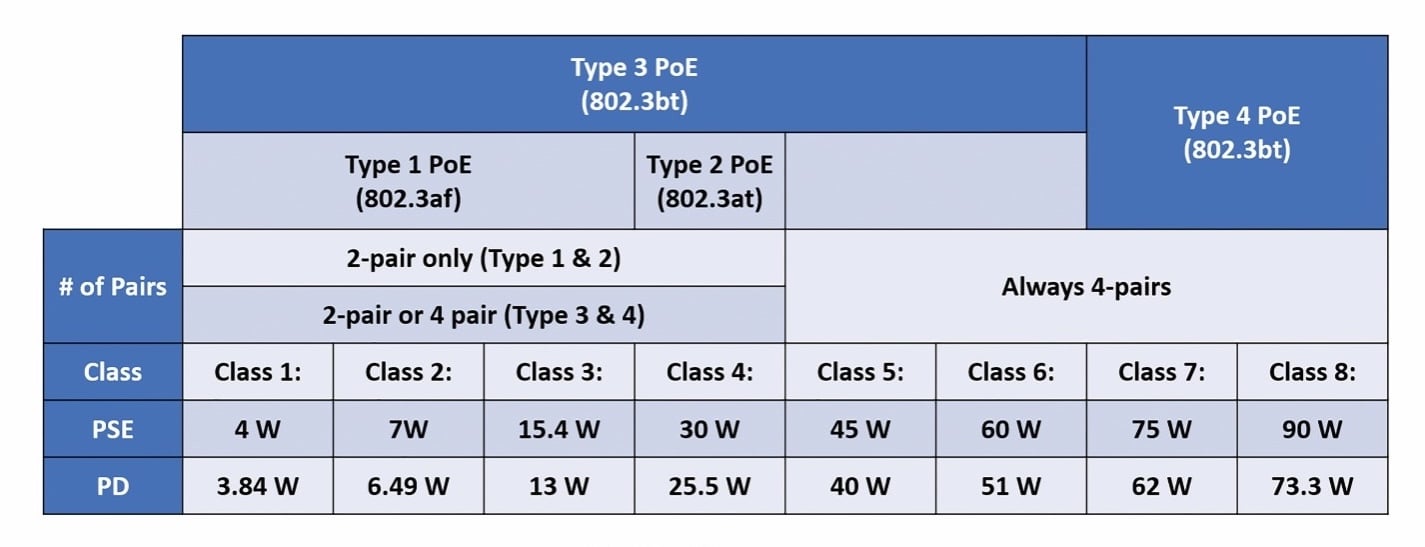
IEEE PoE figures are commonly quoted at the power-sourcing equipment, usually the switch. The usable power at the powered device is lower because energy is lost in the cabling. For a maximum-length standards-compliant channel, current vendor guidance commonly uses the following planning values:
Type 1, IEEE 802.3af, supplies up to 15.4 W at the source and about 12.95 W at the device. Type 2, IEEE 802.3at, supplies up to 30 W and about 25.5 W at the device. IEEE 802.3bt Type 3 uses four pairs for up to 60 W at the source and about 51 W at the device. Type 4 provides up to 90 W at the source and about 71 W at the device.
These are maximum standard values, not a promise that every port on every switch can deliver them simultaneously. Check the switch model, installed power supplies, per-port capability, total chassis budget, operating temperature and redundancy mode. Also verify the endpoint’s supported negotiation method rather than assuming that a high-power port will automatically deliver the required class.
Calculate the total switch budget, not only the port rating
A 48-port switch with PoE++ labels may still have a total power budget far below 48 times the highest per-port rating. Build a budget from the maximum allocation for every connected device. Add proposed expansion ports and include non-AV loads such as wireless access points or cameras if they share the switch.
Confirm how the switch reserves power. Some designs allocate according to the detected class; others can refine the reservation through LLDP or vendor-specific negotiation. If negotiation is absent or misconfigured, the switch may reserve more power than the device normally consumes, reducing the number of ports that can be powered.
Design for the reduced-capacity state. If redundant power supplies are required, calculate how many AV devices remain powered after one module fails. If two switches share the system, state which endpoints move or shut down after a failure. The power budget should cover the accepted resilience condition, not only normal operation.

Treat cabling as part of the power system
PoE depends on the complete channel: permanent cable, patch panels, connectors, consolidation points and patch leads. Poor termination, undersized conductors or excessive resistance can reduce voltage at the device even when data appears to pass. Copper-clad aluminium cable should not be accepted for a standards-based permanent installation.
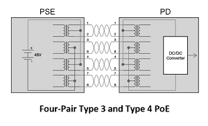
Higher-power IEEE 802.3bt uses all four pairs. DC resistance unbalance within a pair or between pairs can prevent the current from sharing correctly. Large cable bundles and high ambient temperatures can also increase heat and insertion loss. The cabling designer should consider conductor size, bundle size, pathway ventilation, channel length and the applicable local electrical and building requirements.
Specify the test standard before installation. A simple wiremap or link light does not prove that the channel supports the required data rate and PoE load. Retain certification results under the same cable identifiers used on drawings, switch-port schedules and field labels.
Coordinate PoE with bandwidth and network policy
Power and data share the same connector, but they are separate design questions. A port may provide enough watts while lacking the speed, multicast configuration, VLAN access or quality-of-service policy required by the AV application. Record both the electrical allocation and the network configuration for every endpoint.
The AV-over-IP network readiness guide explains how bandwidth, multicast, VLANs, timing and switch capacity should be accepted as one network design. Apply the same discipline to PoE endpoints: stable naming, approved firmware, monitored ports and a documented path between AV devices and their management services.
Avoid unmanaged midspan injectors unless the design explicitly requires them. An injector can solve one power problem while hiding the endpoint from switch-level power monitoring, complicating UPS coverage or introducing a slower network interface. If injectors are used, document their location, data rate, power standard and replacement part.
Plan UPS runtime, restart order and cooling
Centralised PoE can improve resilience because one UPS can support the switch and many endpoints. It also concentrates load in the rack. Calculate UPS demand from the switch’s actual AC input under the accepted PoE load, not from the number of powered devices alone. Include network core equipment, control processors and any local displays or compute devices needed for a usable room.
Define the recovery sequence after an outage. Some endpoints take longer to boot than the switch; others may attempt to negotiate power at the same time. Test whether the switch grants all required allocations after a cold start and whether room controls recover without manual intervention. A system that works after a staggered engineer startup may fail after a building-wide power restoration.
PoE load increases heat inside the switch and rack. Confirm airflow, ambient temperature, rack spacing and the effect of redundant power supplies. Monitoring should alert support teams to denied power, overload, temperature and power-supply faults before users report that a microphone or touch panel is offline.
Commission the installation under realistic load
Commission with every planned endpoint connected and operating. Record the negotiated class, allocated power, actual draw where available, link speed, VLAN and switch port. Start calls, enable cameras and loudspeakers, exercise touch panels and run the busiest credible room scenario while checking switch power and error counters.
Test long cable routes and the highest-power devices first. Verify cold start, switch restart, UPS transfer and the agreed power-supply failure state. If ports are prioritised, disconnect and restore power in a controlled test to confirm that critical devices remain available and lower-priority loads behave as documented.
Use the AV commissioning checklist for China offices to connect these PoE checks with rack inspection, signal testing, user scenarios, issue ownership and signed acceptance. Do not close a power fault by moving a device to a different port unless the budget, port schedule and documentation are corrected.
Hand over evidence that operations can maintain
The handover pack should include the powered-device schedule, PoE type and class, maximum device demand, switch model, power-supply configuration, total and reserved budget, port priorities, UPS assumptions, cabling certificates, switch-port map, configuration backup and the full-load test record.
Provide a change rule for adding or replacing an endpoint. The reviewer should confirm the new device’s maximum demand, supported negotiation, data rate, cable test status, port configuration and effect on normal and failure-state budgets. This prevents a seemingly small room addition from exhausting power needed elsewhere.
Finally, name the owners for switch configuration, AV endpoint support, cabling faults and manufacturer escalation. PoE makes installation cleaner only when power responsibility remains visible after the project team leaves.