
Define the acceptance boundary before cables are installed
Begin with a test schedule that describes what is being accepted. For each link type, state the cable category or fibre specification, topology, connector type, maximum design length, permanent-link or channel boundary, application, test standard and pass limit. Identify whether consolidation points, modular plugs, patch panels, equipment cords, splices and pre-terminated trunks are inside or outside the measurement. Without that boundary, two valid-looking reports can measure different systems.
The project specification should also name the instrument accuracy level, software and firmware baseline, calibration requirement, test direction, fibre wavelengths, reference method and deliverable file format. An AV integrator in China should coordinate these points with the client, network team, cabling contractor and manufacturer warranty requirements before termination begins. Acceptance criteria written after testing often create avoidable retests and disputes.

Distinguish certification from verification and qualification
A basic wire-map or continuity tester verifies that conductors are connected and can reveal opens, shorts, reversals and split pairs. A qualification tester estimates whether an installed link can support a named network application. Certification is different: it measures all parameters required by a selected cabling standard and applies the standard's pass or fail limits. A link that carries traffic today is not automatically certified for its specified category or class.
For copper, certification goes beyond pinout and length to measurements such as insertion loss, return loss, near-end crosstalk, power-sum crosstalk and delay. For fibre, basic or Tier 1 certification covers polarity, length and insertion loss, while extended or Tier 2 testing adds OTDR characterisation of individual events. Choose the level required by the design, warranty and risk; do not substitute a lower test because active equipment happens to connect.
Choose the correct copper link model and adapters
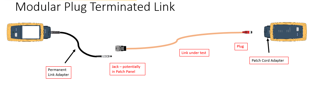
A permanent-link test normally measures the fixed installed cabling between termination points and excludes user patch cords. A channel test includes the permanent link plus the patch and equipment cords defined by the channel. Modular-plug-terminated links, consolidation points and direct-connect devices need the matching test configuration and approved adapters. Testing a fixed link with channel adapters can hide the performance of the installed connectors behind a different acceptance limit.
Select the exact limit in the tester rather than relying on a generic label such as Cat 6A. ANSI/TIA-568.2-E, released by TIA in November 2024, is the current balanced twisted-pair cabling and components revision in that series. ISO/IEC 11801-1:2017 remains the general customer-premises cabling document and has an amendment. A project may specify one standards family, local requirements or a manufacturer-specific warranty limit, so the report must identify the actual selection.

Review the full copper certification result
Confirm that every expected cable identifier appears in the result set and that the selected test limit matches the design. Review wire map, length, propagation delay, delay skew, DC loop resistance, insertion loss, return loss, NEXT, power-sum NEXT and the far-end crosstalk parameters required by the limit. Shielded systems also need shield continuity or integrity evidence. Retain plot data rather than only a one-line pass summary, because plots reveal margin and help diagnose later faults.
Treat a marginal pass carefully. The tester may display the worst-case margin and indicate whether measurement uncertainty affects the result. Re-terminate, inspect or replace the link when its margin is inconsistent with comparable runs or the project threshold, even if a single automated test says pass. Do not average away failures across a bundle. Each installed link is an asset and must meet its own acceptance limit.

Add PoE-focused resistance checks where power matters
AV-over-IP endpoints, cameras, control panels, wireless access points and other building devices increasingly receive data and power through the same balanced pairs. Excessive loop resistance wastes power, while resistance unbalance within or between pairs can produce unequal current sharing. Include the appropriate DC resistance and unbalance measurements when the cabling will support PoE, especially higher-power four-pair applications.
Fluke Networks notes that certification limits and field-test requirements differ, so the required PoE measurements must be selected deliberately rather than assumed to be part of every default test. The Power over Ethernet AV design guide explains the wider relationship between switch power budgets, cable bundles, endpoint classes and commissioning. Cabling acceptance should provide the physical-layer evidence that the PoE design depends on.
Inspect, clean and certify every fibre path
Inspect both connector end faces before mating, including test reference cords and equipment ports. If an end face fails inspection, clean it with an appropriate fibre tool and inspect it again before connection. A dust cap does not prove cleanliness. Contamination can increase loss and reflectance, damage a mated end face and invalidate otherwise careful measurements.
Tier 1 testing with an optical loss test set establishes polarity, length and total insertion loss at the required wavelengths. Set the reference correctly and record the test method, fibre type, wavelength and loss budget. Tier 2 or extended testing adds an OTDR to locate and characterise connectors, splices, bends and other events. An OTDR complements rather than replaces the optical loss measurement; the total end-to-end insertion-loss result still comes from the OLTS. Where bidirectional OTDR testing is required, retain results from both directions and the averaged event data.
Control identifiers, retests and report integrity
Cable identifiers in the tester must match the drawings, patch-panel labels, outlet labels and asset schedule exactly. Configure the project before field testing so technicians do not create duplicate names, omit rooms or overwrite results. Record the tester model, serial number, calibration status, software version, operator, date and selected limits. Synchronise the tester clock before work starts so defect and retest records form a reliable timeline.
Keep the original failed result, the corrective action and the final pass rather than deleting the history. Common remedies include re-terminating a connector, correcting pair untwist, replacing a damaged patch lead, cleaning fibre, removing a bend or repairing a splice. A complete report should reconcile the planned link count with tested, passed, failed, retested and excluded links. Unexplained gaps are a handover defect even when the submitted results are green.
Use cabling evidence during AV and IT handover
Deliver native test files as well as readable PDF reports, because native results preserve plots and can be re-analysed. Include the approved schedule, cable and connector data sheets, as-built routes, labelling index, warranty documents, calibration evidence, fibre inspection images, loss budgets, OTDR event maps where specified, defect log and spare-core record. Protect the files from later editing and store a controlled copy with the wider project documentation.
Cabling reports should be reviewed before application commissioning, not appended after the rooms are already accepted. The AV-over-IP network readiness checklist shows how physical links, switch configuration, multicast, QoS and monitoring fit together. The commercial AV commissioning checklist for China provides the broader functional handover framework. Any post-handover re-termination, patching redesign or cable replacement should trigger a focused retest and report update.